| Ch 9. External Flow | Multimedia Engineering Fluids | ||||||
| Drag | Lift |
Boundary Layer |
|||||
| Lift | Case Intro | Theory | Case Solution |
| Chapter |
| 1. Basics |
| 2. Fluid Statics |
| 3. Kinematics |
| 4. Laws (Integral) |
| 5. Laws (Diff.) |
| 6. Modeling/Similitude |
| 7. Inviscid |
| 8. Viscous |
| 9. External Flow |
| 10. Open-Channel |
| Appendix |
| Basic Math |
| Units |
| Basic Equations |
| Water/Air Tables |
| Sections |
| Search |
| eBooks |
| Dynamics |
| Fluids |
| Math |
| Mechanics |
| Statics |
| Thermodynamics |
| Author(s): |
| Chean Chin Ngo |
| Kurt Gramoll |
| ©Kurt Gramoll |
|
|
|||||
|
The concept of drag was introduced in another section, and the concept of lift will be discussed in this section. |
|||||
| Lift |
|||||
|
|
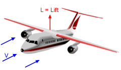
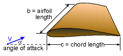
When fluid flows over an immersed body, forces will be exerted on the body. The resultant force parallel to the fluid motion is referred to as the drag while the resultant force perpendicular to the fluid motion is known as the lift. Determining lift is obviously important in the design of airplanes, and the lift (L) is often expressed in terms of the lift coefficient (CL) as where ρ is the fluid density; A is the characteristic area and V is the upstream velocity. The planform area (A = bc) is often used as the characteristic area in the study of airfoils. In general, the lift coefficient is a function of the body shape, Reynolds number and angle of attack (see below). Take flow over an airfoil for example. The airfoil is one of the designed shapes known best for generating lift. The angle between the free stream velocity and airfoil chord line is referred to as the angle of attack (α). Lift is produced by generating a pressure difference between the top and bottom surfaces. When flow is past a symmetric airfoil with no angle of attack (i.e., the free stream velocity is parallel to the airfoil chord line), no lift will be produced due to the symmetric flow field. In order to generate lift, either the airfoil should be non-symmetric or the angle of attack nonzero. |
||||
 The plot of CL/CD as a Function of the Angle of Attack for a Typical Airfoil 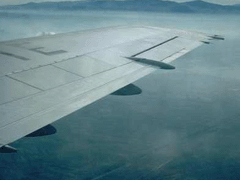 Flaps on a Passenger Jet |
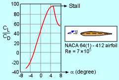
The plot of the lift-to-drag coefficient (CL/CD) as a function of the angle of attack for a typical airfoil is shown in the figure. By increasing α, the lift-to-drag ratio increases and reaches a maximum value (i.e., the most efficient angle of attack). A further increase of α will produce a sudden drop in lift (or an increase of drag), and this undesirable phenomenon is known as stall. Nowadays, the wings of airplanes are equipped with adjustable leading edge and trailing edge flaps, as shown in the figure, to alter the angle of attack. From the discussion of flow past a rotating cylinder, according to the Kutta-Joukowski law, the generated lift is directly proportional to the density, upstream velocity and the strength of the vortex. The lifting effect for rotating bodies in a free stream is called the Magnus effect. Similarly, there is no lift for flow past a fixed sphere due to symmetric flow conditions. However, when the sphere is rotated, the lift is generated due to a pressure difference. For example, a baseball pitcher can throw a curve ball by spinning the ball. |
||||
| Basic NACA Airfoil Shapes |
|||||
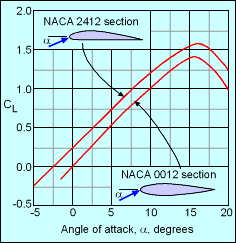 The plot of just CL as a Function of the Angle of Attack for Airfoils NACA 2412 and NACA 0012 |
In the early years of aviation there was a government agency called NACA (later became NASA). They pioneered methods to describe basic airfoil shapes for standardization. The most commonly used method is the four-digit airfoils, such as the NACA 2412 airfoil. The digits describe three important parameters, the maximum camber height of the mean center line (m), the location of the maximum camber (p), and the maximum airfoil thickness (t). The first digit gives the camber height (m) in percent (2 = 0.02), the second digit gives the location in tenths (4 = 0.4) and the last two digits gives the thickness in percent (12 = 0.12). These numbers are used in a simple polynomial equation to generate the airfoil shape. Usually, the overall chord length of the airfoil (c) is unit length of 1. The diagram below illustrate a NACA 5512 airfoil. There are other methods to describe airfoils, including the five-digit and six-digit methods, also developed by NACA. |
||||
 |
|||||
| Basic Airfoil Pressure Distribution |
|||||
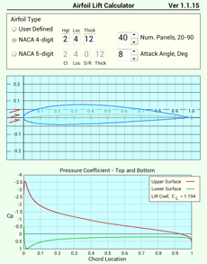
The main purpose of any airfoil is to maximize lift and minimize drag. To assist in developing optimal airfoil shapes, both experimental and numerical simulations should be conducted. For experimental, generally, only the lift and drag forces are found. With numerical simulations, pressure distributions are determined, and then that pressure can be used to find the final lift and drag. Below, is a simple airfoil shape generator that uses the NACA four-digit series, NACA five-digit series, and user determined shape as input. The program uses the vortex panel method to determine approximate pressures around the airfoil. There are more accurate methods but require greater input information and more CPU time. The vortex panel method is surprising good for most situations. |
|||||
| Airfoil Lift Calculator Tool |
|||||
|
For basic airfoils, the lift can be calculated using a numerical method called, the Vortex Panel method (see "Fundamentals of Aerodynamics", John Anderson, McGraw-Hill). This technique can only estimate the lift and not the drag. Drag is much more difficult to simulate numerically, and requires substantial computing power to solve the full Navier Stokes equations. An mobile app can be used on either iOS or Android. For Android mobile devices, "Airfoil LIft Calculator", can be downloaded at Google Play. For iOS (Apple) mobile devices, "Airfoil Lift Calculator", can be downloaded at iTunes. |
||||
Practice Homework and Test problems now available in the 'Eng Fluids' mobile app
Includes over 250 free problems with complete detailed solutions.
Available at the Google Play Store and Apple App Store.
